
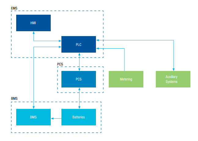
Basic structure of ESS inlcude EMS, PCS, Lithium batteries and BMS
It’s important for solar + storage developers to have a general understanding of the physical components that make up an Energy Storage System (ESS). It gives off credibility when dealing with potential end customers to have a technical understanding of the primary function of different components and how they inter-operate with one another. At Energy Toolbase, our team fields numerous questions on this topic, which is why we decided to summarize our answers into a blog.
OSM focus entirely on lithium-ion (LFP) based batteries, which are the most widely deployed type of batteries used in stationary storage applications today. The U.S. Energy Information Administration (EIA) trends report on the U.S. storage market found that lithium-ion batteries currently represent more than 90% of the operating battery capacity in the market.

EMS
The EMS (Energy Management System), by means of an industrial PLC (programming based on IEC 61131-3) and an industrial communication network, manages the operation and control of the distribution system and must allow the control of variables of interest of the storage system and the monitoring of electrical quantities, operational status and alarms of the entire system (PCS, BMS, renewable sources, generator, etc.). The EMS has a local access platform (SCADA + HMI) with a real-time status monitor, which allows viewing monitoring data, alarms, reports, and charging and discharging curves, sending control commands, changing operating modes, among others. It is also possible to access this system through a remote platform (online access).
The energy management system handles the controls and coordination of ESS dispatch activity. The EMS communicates directly with the PCS and BMS to provide high-level coordination of the various components on-site, often by referencing external data points. The EMS is responsible to make decisions on when and how to dispatch, which is generally driven by an economic value stream, such as demand-charge management, time-of-use arbitrage, or solar self-consumption. EMS software attempts to optimize the performance of the ESS by weighing long term cycling and capacity degradation with the return on investment of the asset. This involves being aware of the BMS and PCS limitations and recognizing when the energy storage system can be used most effectively.
The programmed behavior and sophistication of the EMS deployed can vary based on application. Certain sites, customers, and regulatory environments only require a simple coordinated discharge during a pre-specific Time-of-use (TOU) window. In other cases, the EMS may need to employ advanced machine learning algorithms to co-optimize multiple value streams concurrently, both behind and in-front of the meter. The operational mode of the EMS for a specific site is generally determined in advance by simulating the control strategies for the specific project. The EMS is given the responsibility to make proper decisions to maximize required outcomes from the asset while simultaneously balancing those decisions with long term asset management of the system.
The EMS also serves as a single collection point for the performance data of an ESS. The EMS is optimally situated to gather, transmit, and analyze ESS information coming from the site. This places the EMS and its users in the best position to maintain the asset and address any issues on site. A proper EMS will be accompanied by a robust data collection and presentation platform which enables end-users and responsible parties access to information on a regular basis for system reporting as well as diagnostic exercises.
PCS
The PCS (Power Converter System) is the interface between the DC link of the batteries and the AC busbar of the inverter. In addition, the PCS monitors electrical variables, alarms of interest and is fully integrated with the operation, control and energy management (EMS) system.
Like a solar PV system, a Li-ion battery bank requires an inverter to produce an alternating current (AC) that is usable in buildings. Also referred to as Power Conditioning Systems or battery hybrid inverters, these devices are more dynamic than a typical PV inverter because they are capable of operating bi-directionally. This means power can flow from DC to AC or vice-versa, which effectively enables the ESS to both charge and discharge. The PCS directs the flow of energy by commanding the battery’s charge and discharge behavior. In order to do so, the hybrid inverter needs to be well informed on the available capacity of the battery, so it knows to stop charging when the battery is full. In this fashion, the Power Conditioning System is responsible for the low-level electrical functions on site. These reactions can be driven by metered information on-site or through external signals about when to charge and discharge the system for maximum effect.
In the context of a PCS, it is important to distinguish between AC-coupled vs DC-coupled systems. For a solar + storage system, there is a choice between connecting the battery directly on the same DC bus where the PV lands (DC coupling) or connecting external of the PV system on the AC side of the PV inverter (AC coupling). Therefore, AC vs DC coupling refers to how the battery is interconnected to the rest of the system. A DC-coupled system has only one inverter, shared between the PV and battery. Whereas an AC-coupled system has its own dedicated inverter strictly connected to the battery. An AC-coupled system can only draw from AC energy to charge. A DC-coupled system can charge directly from the DC-coupled PV or via AC energy on the opposite side of the hybrid inverter. There are pros and cons to each architecture, which we will discuss in a separate article. When making this design decision storage developers need to consider various factors, including electrical constraints, system efficiency, interconnection limitations, monitoring requirements, policies and regulation, and site access.
BMS + Batteries
The BMS (Battery Management System) manages the bank of rechargeable batteries, preventing the pack from operating
outside
The Battery Management System (BMS) is a core component of any Li-ion based ESS and performs several critical functions. The primary job of the BMS is to protect the battery from damage in a wide range of operating conditions. It does so by ensuring that the battery cells operate within their prescribed operating windows for the state of charge, voltage, current, and temperature. This is especially important for high power density Li-ion batteries to prevent fires or explosions caused by thermal runaway and combustion. This software is generally designed specifically by each manufacturer and is insular to the site. A BMS typically does not natively communicate with external devices nor speak a standardized programming language.
The BMS is constantly monitoring critical information of the battery bank from individual cells, battery modules, and racks. This includes recording vital electrical operating parameters as well as electrolyte levels, internal cell temperature and ambient battery enclosure temperature. It may also be coordinating any necessary mechanical HVAC measures. All of this information is collected and used for proper maintenance and runtime estimates of the battery asset. The BMS also ensures that the battery cells remain balanced at the same state of charge. Any imbalance across the battery bank terminals can cause cells to get stressed and lead to a reduction in the overall cycle life of the battery.
At the most basic level, an individual battery cell is an electrochemical device that converts stored chemical energy into electrical energy. Each cell contains a cathode, or positive terminal, and an anode, or negative terminal. An electrolyte promotes ions to move between the electrodes and terminals, which allows current to flow out of the battery to perform work. A cell is effectively the smallest, packaged form a battery can take. These battery cells are combined in a frame to form a module. This is generally done by assembling a fixed number of cells together, connected in either series or parallel. A cluster of battery modules is then combined to form a tray, which as illustrated in the graphic above may get packaged with its own Battery Management System (BMS). For certain types of make and model energy storage systems, trays are then stacked together to form a battery rack.
Monitoring and management function
Data acquisition and management
The monitoring system can communicate through intelligent devices, real-time and timing data acquisition of analog and switching quantities, and all electrical data are directly sampled by AC to ensure high precision and simultaneity of measurement.
Analog acquisition:
Including voltage, current, active power, PCS charge and discharge capacityand ambient temperature and humidity information etc.
State quantity collection:
1) Fire alarm signal;
2) Fire, PCS, BMS fault signals;
Electrical energy collection and management:
1) Accumulated discharge capacity;
2) Accumulated charge capacity;
3)Battery bank SOC, voltage, current, temperature, alarm ect.
PCS running status monitoring
The system can control the startup and shutdown of the energy storage system PCS, and can set the charging/discharging time and charging/discharging power of the PCS.
Monitoring including basic parameters of PCS, normal operation, abnormal operation, fault alarm, charge and discharge state, charging current, discharge current, battery pack voltage, cumulative charge, cumulative discharge amount.
Leave A Comment